Mesh Editor
A tool to create a mesh out of a Bezier surface, upsample with loop subdivision, and visualize Phong shading and environment mapping.
- Overview
- Bezier Patches
- Smooth Shading
- Edge Flip
- Edge Split
- Mesh Upsampling
- Phong Shading and Environment Mapping
Overview
This project explored the geometry of 3D modeling by creating a tool that can display and make simple edits to a COLLADA mesh file. It can tessellate a Bezier surface and upsample a mesh, and implements Phong shading and environment mapping.
I can also use my program to load and shade a custom model that I created in the open-source 3D computer graphics and animation software, Blender!
Bezier Patches
Given a 4-by-4 grid of Bezier control points, I can evaluate all points on the corresponding bicubic Bezier patch using the Bernstein polynomials of degree 3. A Bezier surface can be represented as a continuous set of Bezier curves, parametrized by (u, v) coordinates in the range [0, 1] x [0, 1].
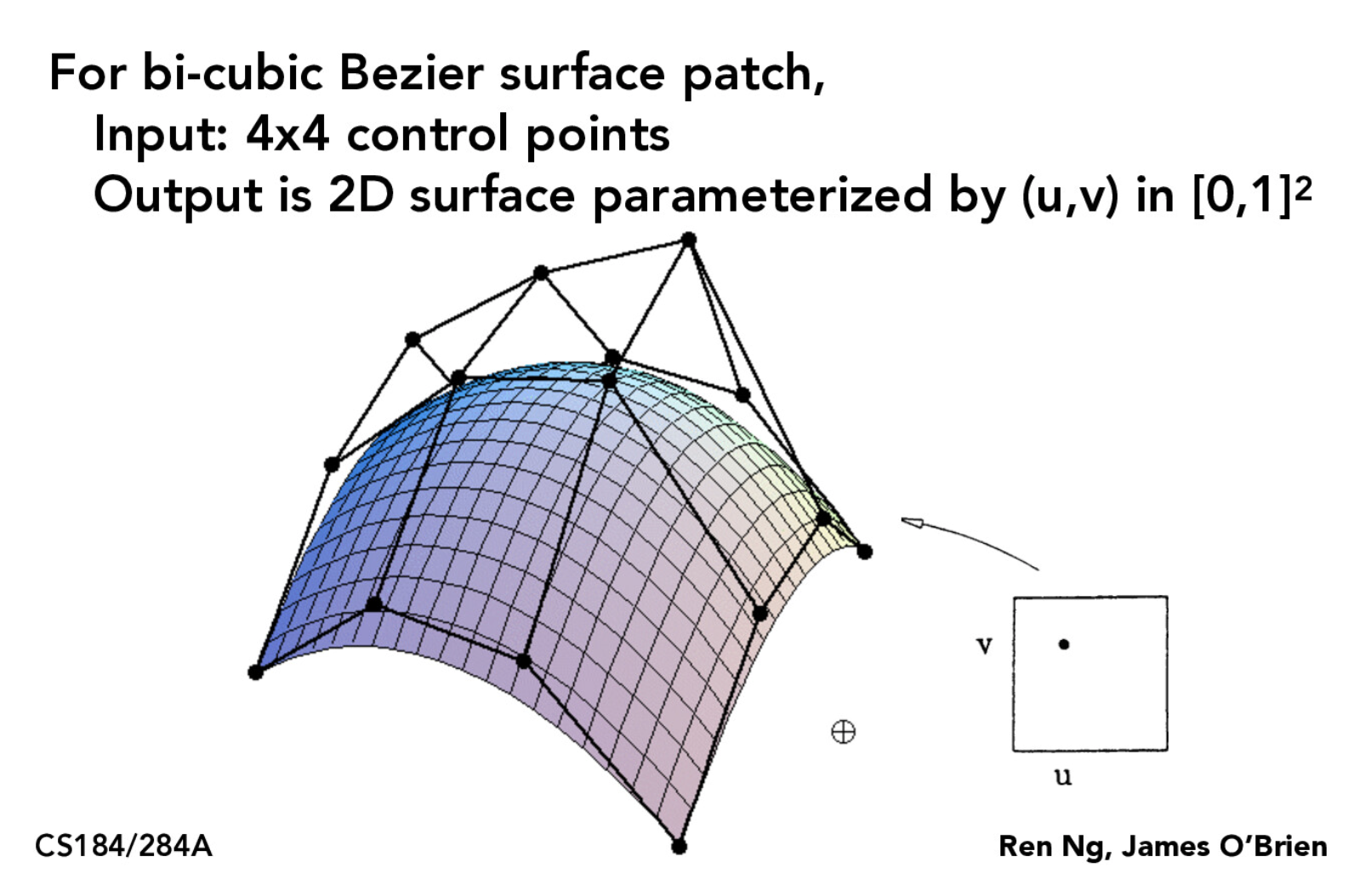
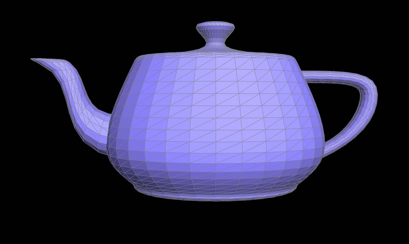
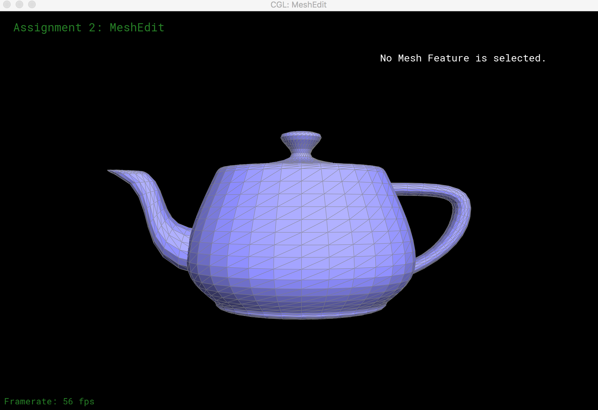
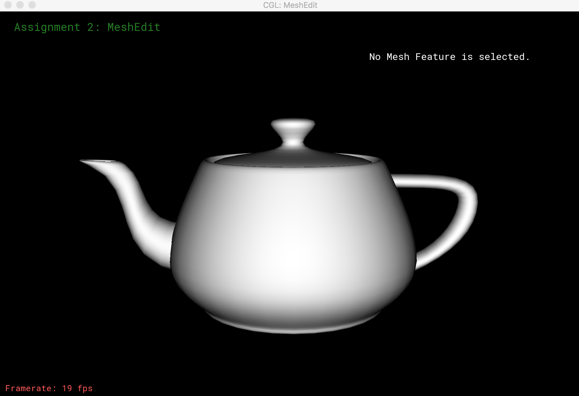
A 9 x 9 grid of evenly spaced (u, v) coordinates were used as sample points to evaluate our Bezier surface. The resulting vectors were then taken 3 at a time to tesselate the surface using triangles. Here, we evaluate the Bezier surface for a teapot mesh.
Smooth Shading
To implement smooth shading, I need to compute the area-weighted average normal for each vertex, which requires iterating through the vertex’s neighboring vertices. We can perform this traversal by using the halfedge data structure for mesh representation.
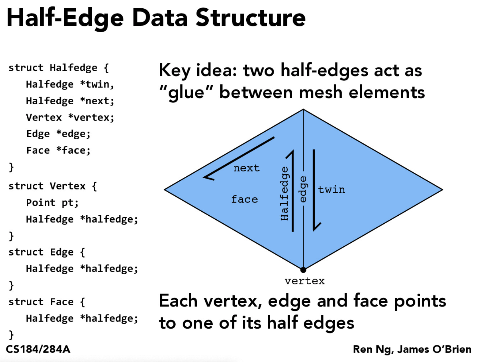
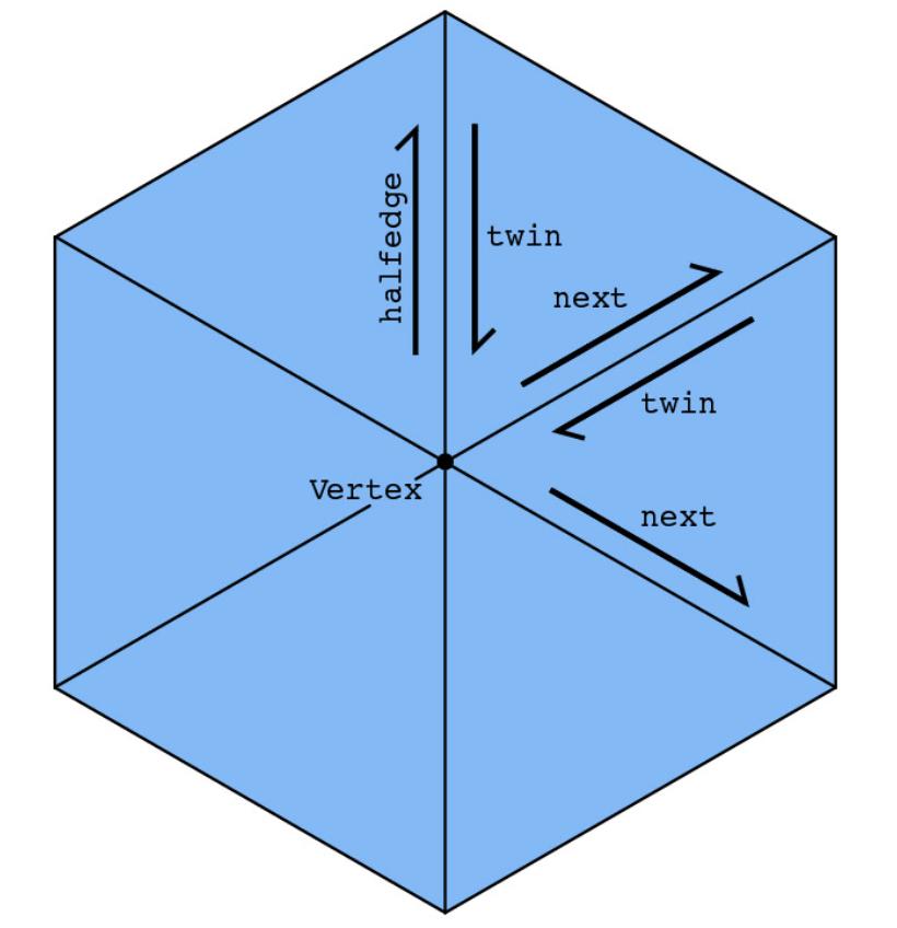
A mesh consists of faces, edges, vertices, and halfedges, which tie together all the other elements. We can iterate through the neighboring vertices around a vertex by starting from the twin of a vertex’s halfedge (so that it points inwards from a neighbor) and then repeatedly taking the twin of the next halfedge, ignoring faces on the boundary.
Edge Flip
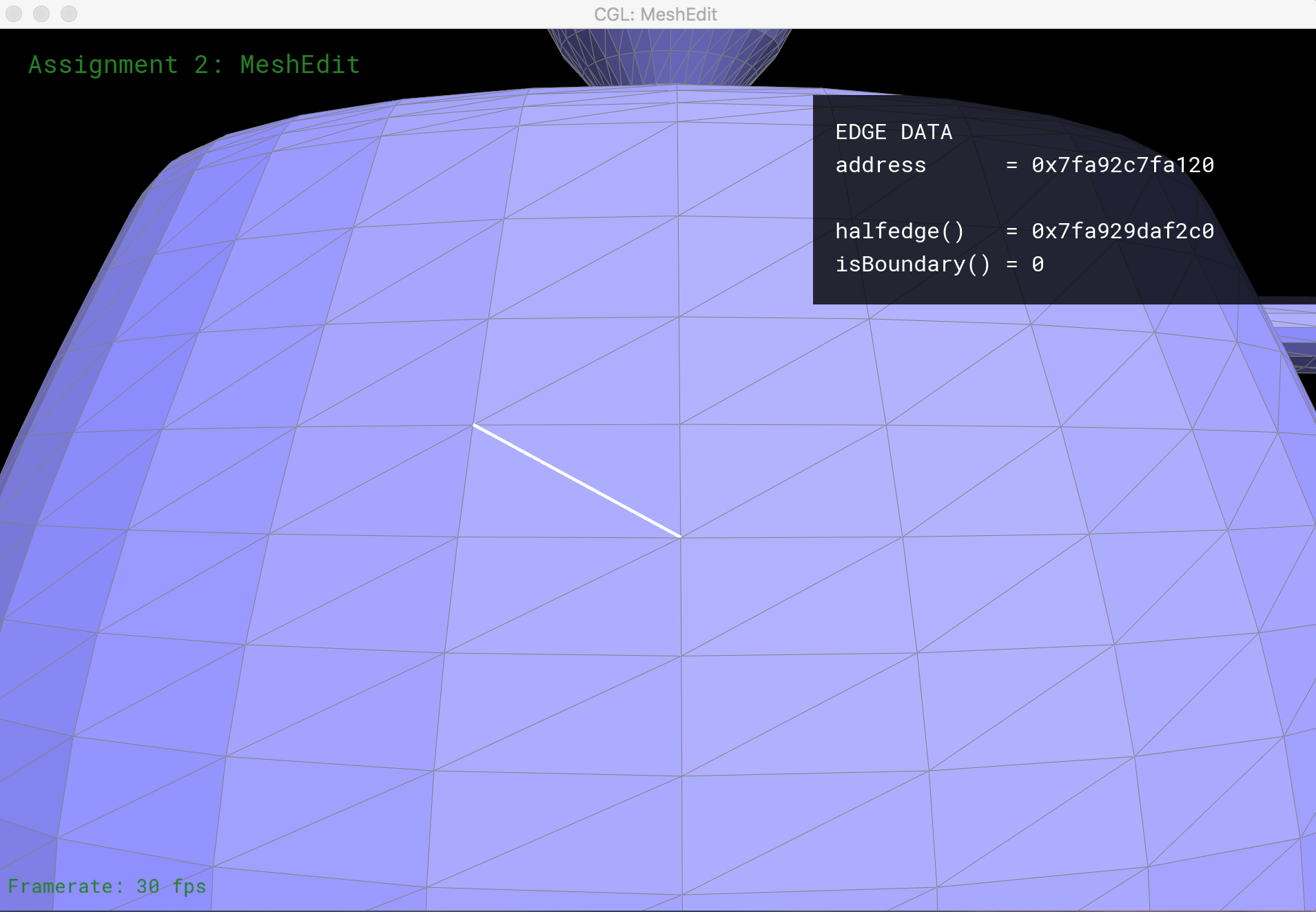
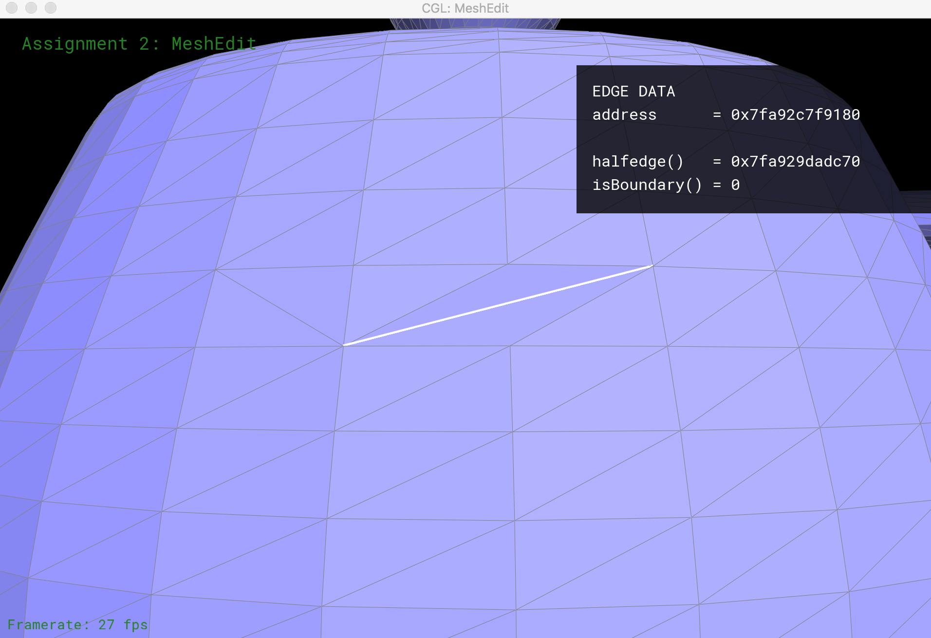
I implement functionality to flip a non-boundary edge in a mesh. Flipping edge cb in the diagram below should create a new edge ad, and give us triangles adc and abd.

This process starts with identifying all elements in the original mesh of a pair of triangles: 6 half-edges, 2 faces, 5 edges, and 4 vertices. We then systematically set the pointers for these elements to their new values (after the edge flip is complete). This operation doesn’t create or destroy any new mesh elements.
Edge Split
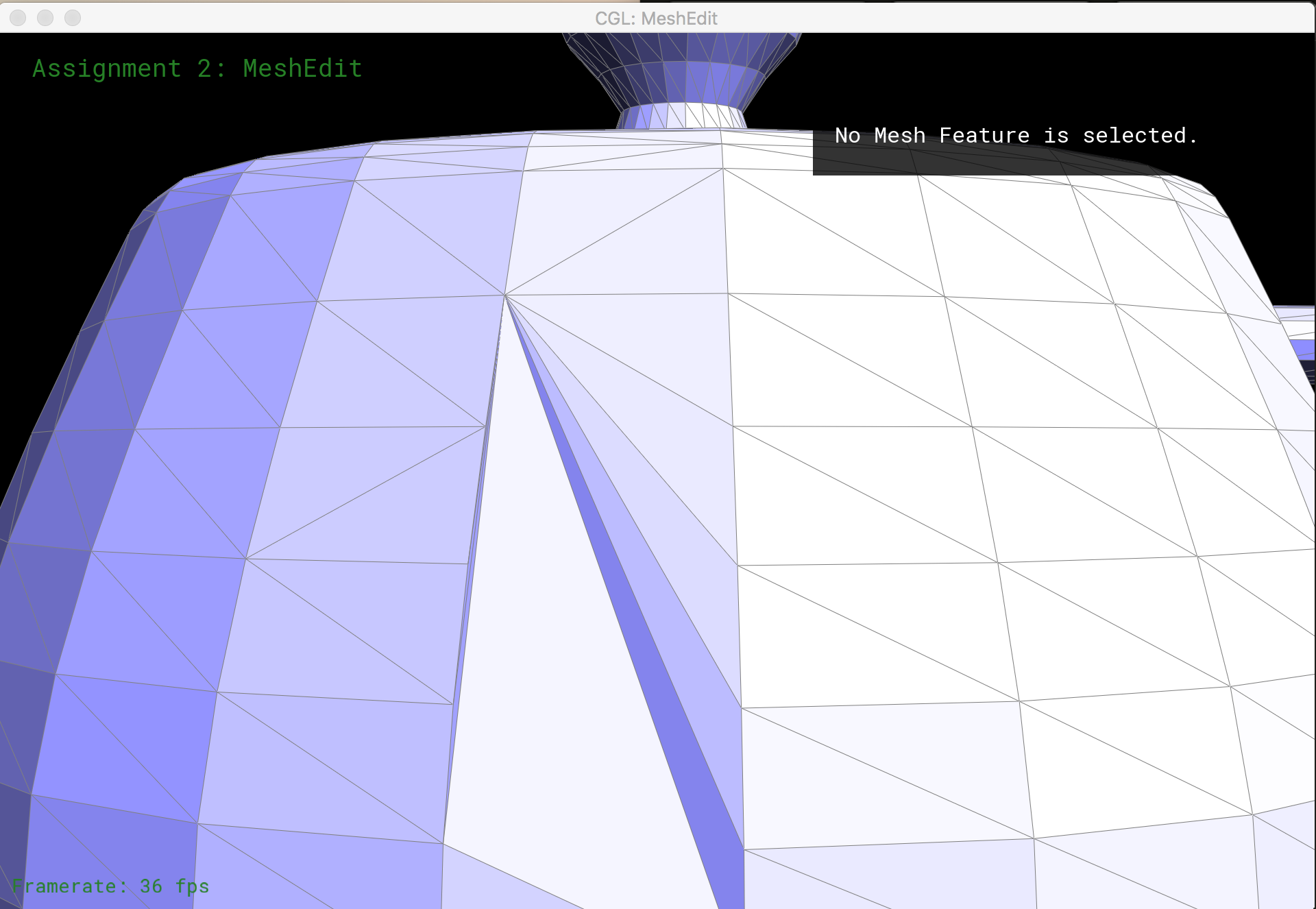
An edge split operation creates 1 new vertex, 3 new edges and 2 new faces.

As before, I begin by identifying all the half-edges, vertices, edges, and faces that are present in the original mesh of a pair of triangles. To split a non-boundary edge, I reassign pointers of the original elements if necessary, and create 1 new vertex, 6 new half-edges, 3 new edges, and 2 new faces, setting their neighbors as appropriate.
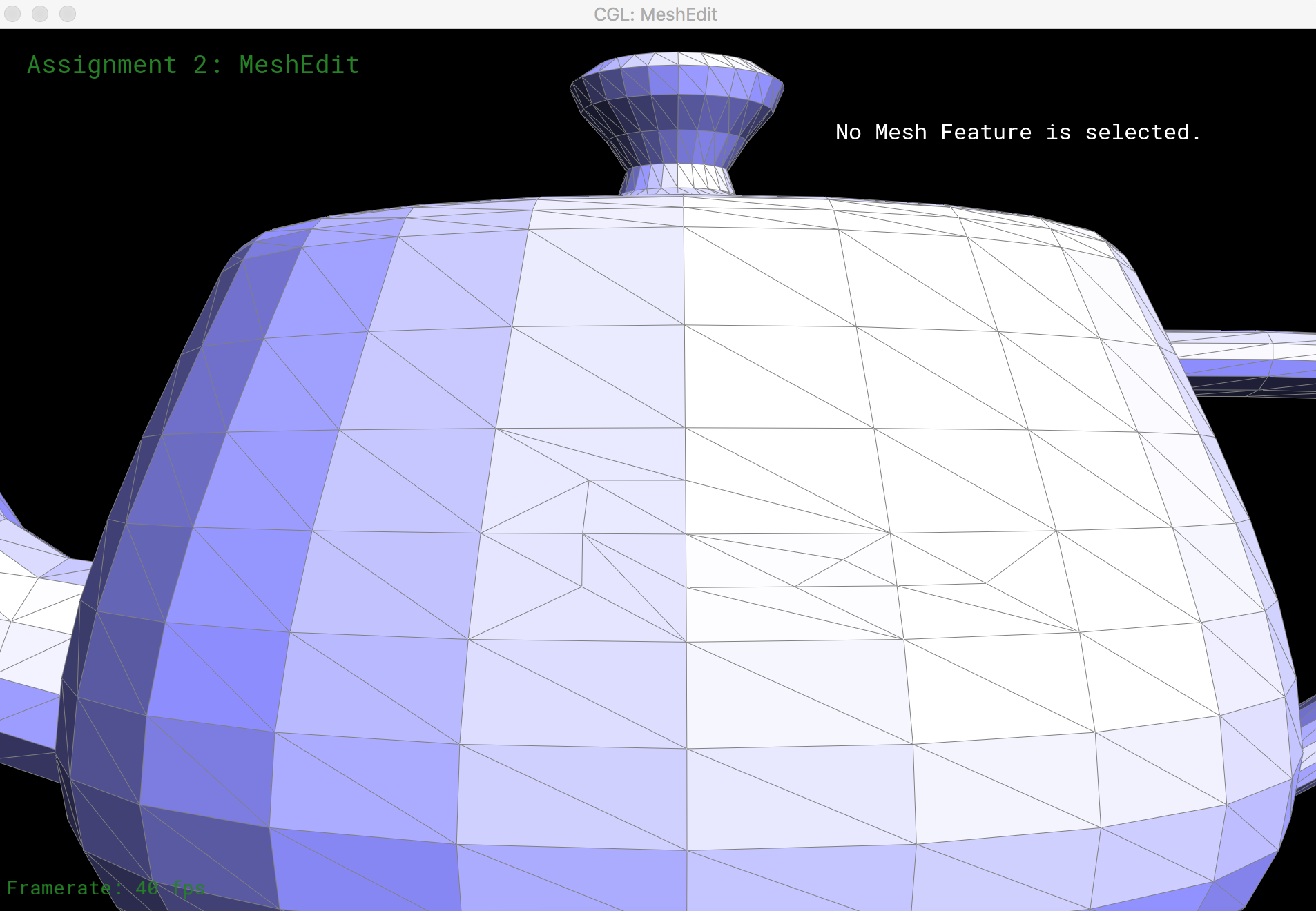
Here is the teapot mesh after multiple edge split operations.
Mesh Upsampling
Once we can flip and split edges, we can upsample a mesh via loop subdivision. The subdivision algorithm:
- split each edge to create a new vertex along every edge in the mesh
- flip new edges that connect an old and a new vertex
- move each vertex to its updated location, a precomputed average of its neighboring vertices before the split
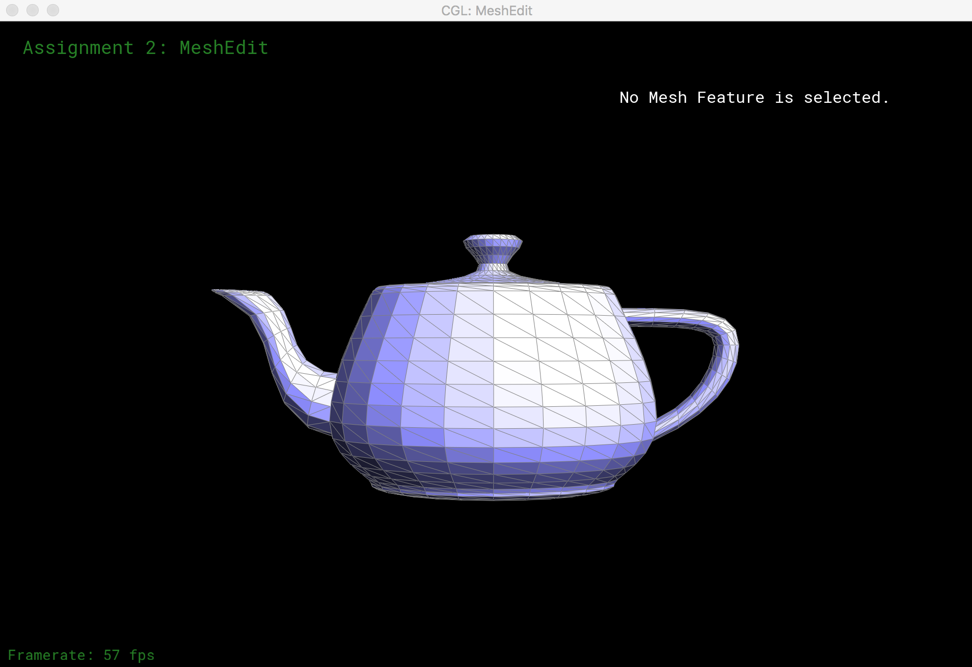
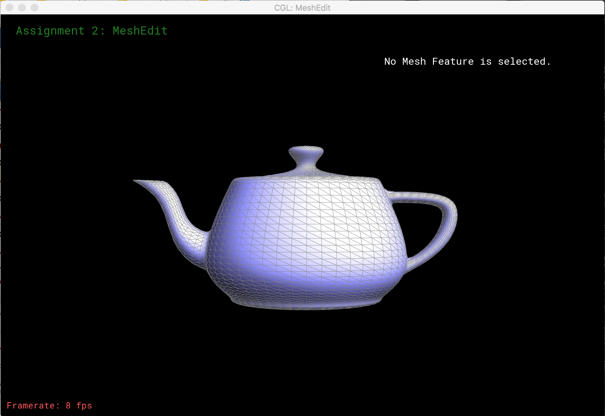
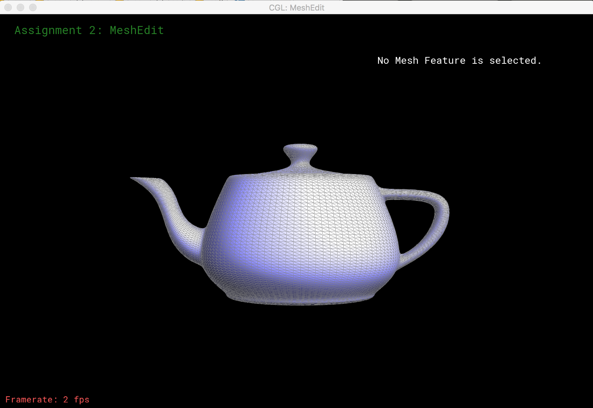
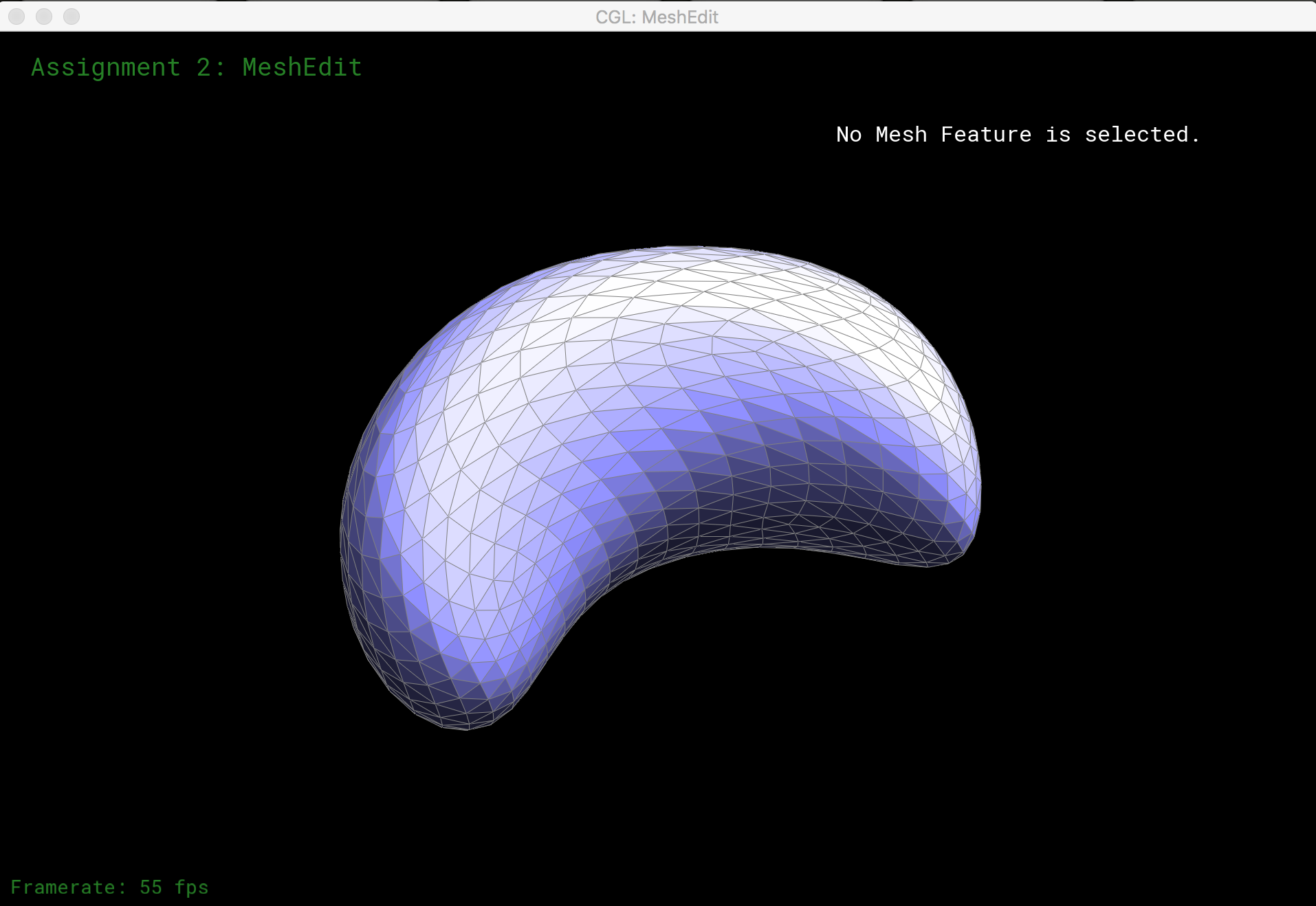
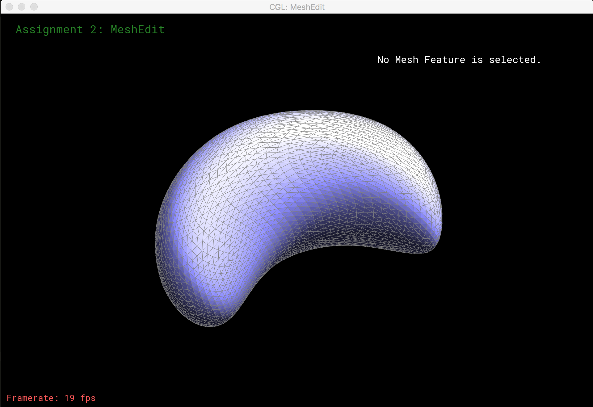
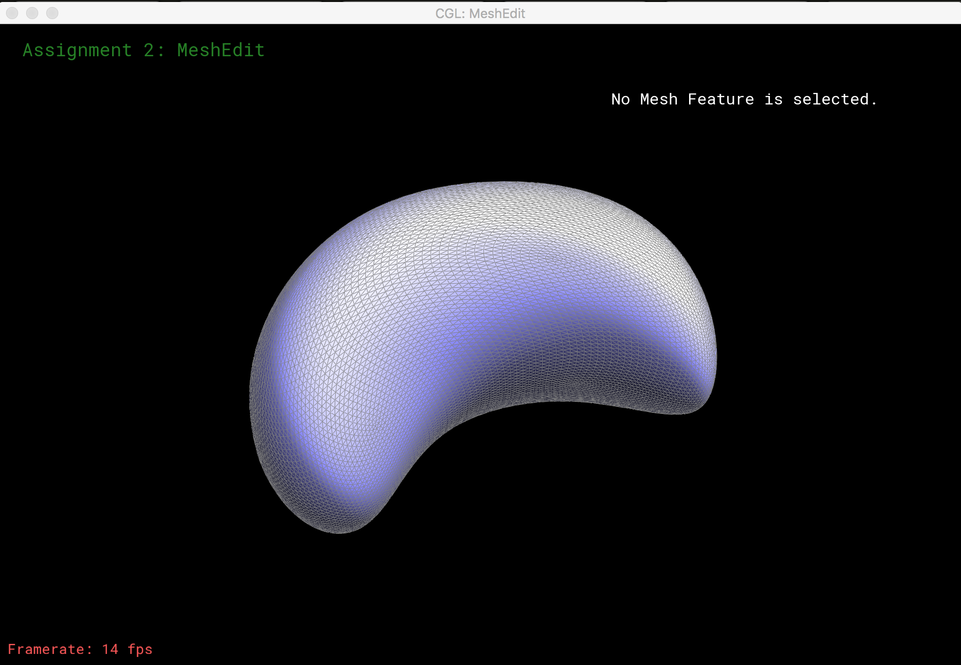
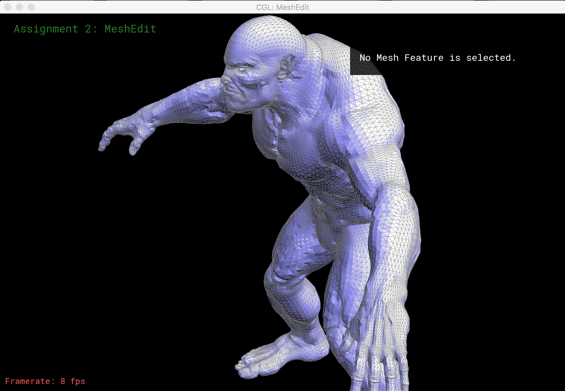
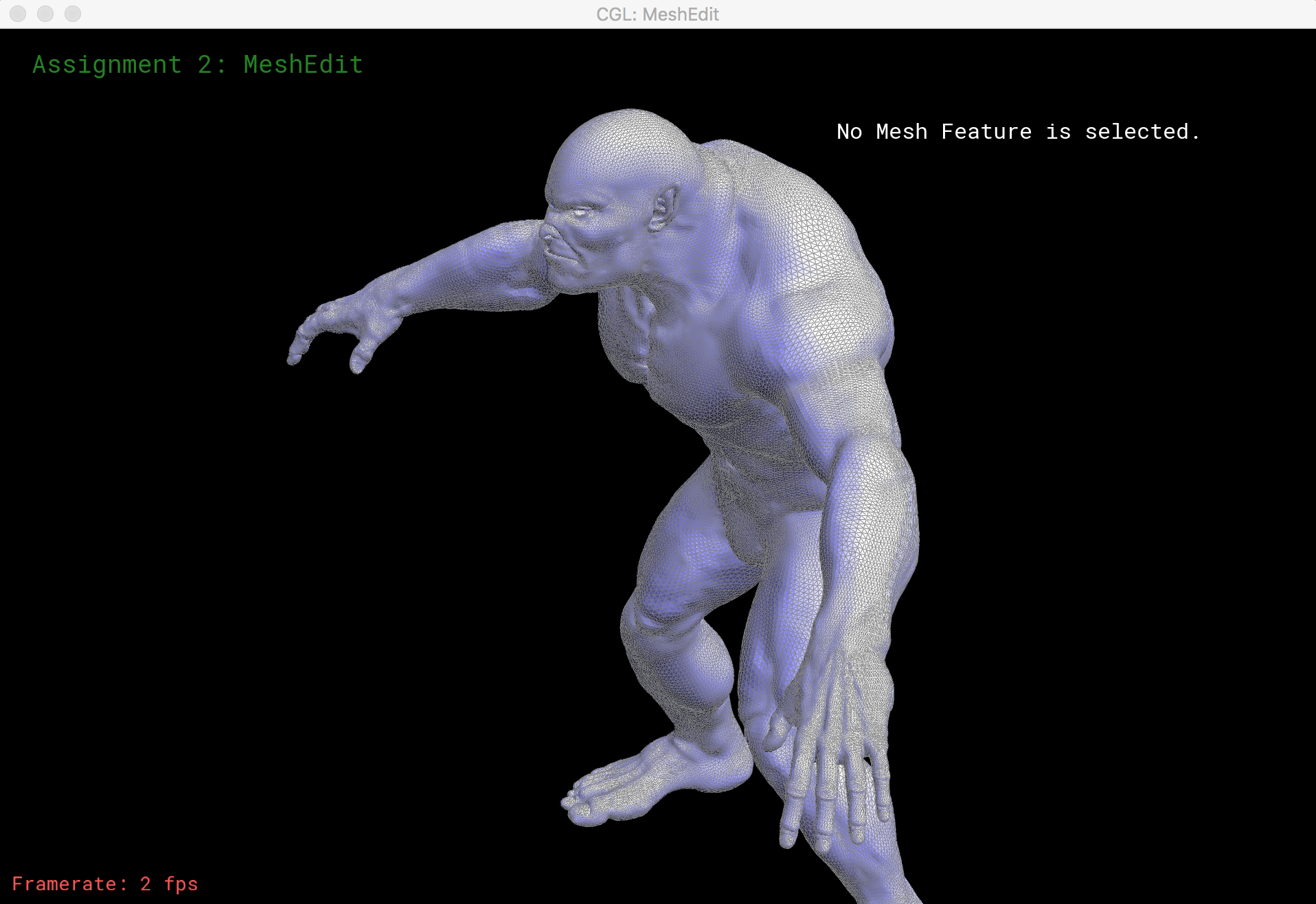
Here is loop subdivision performed on several meshes:
Phong Shading and Environment Mapping
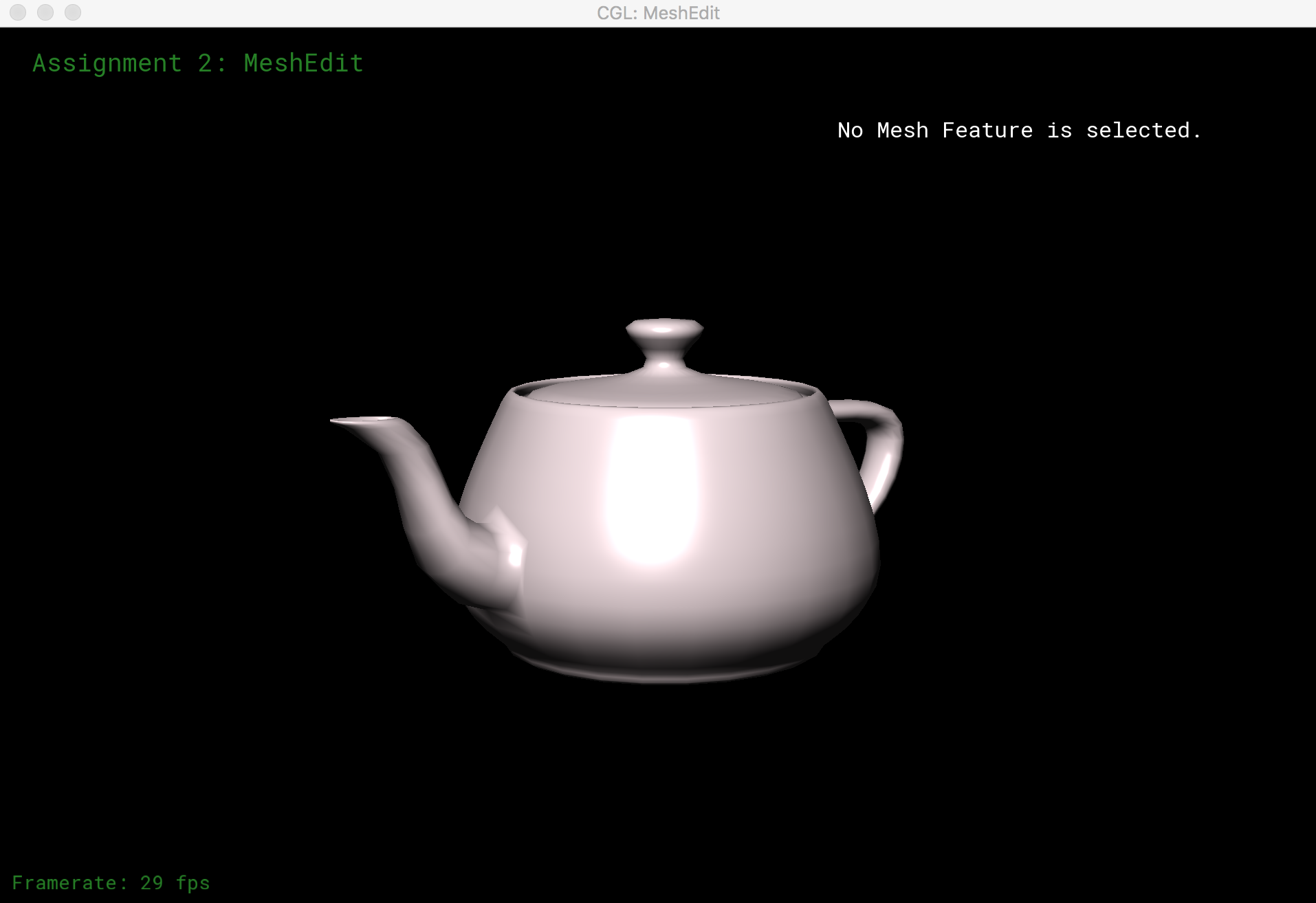
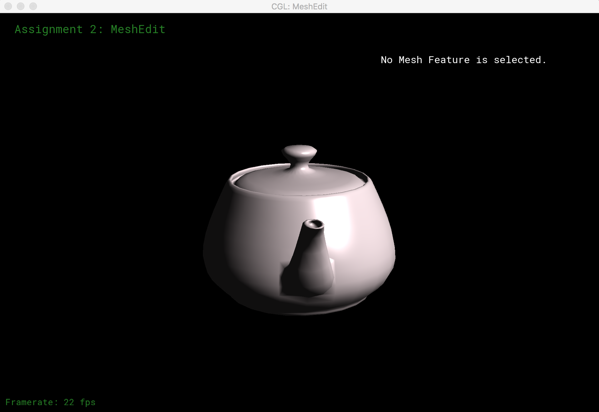
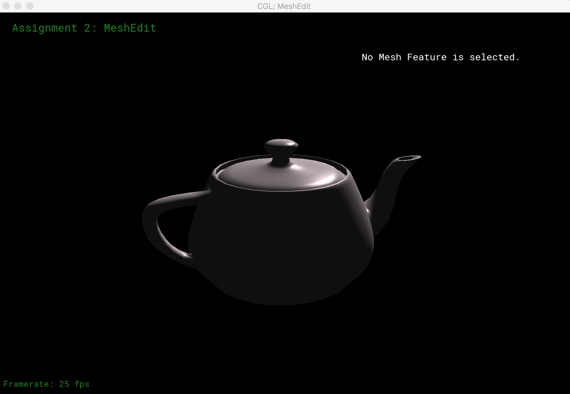
I implemented Phong shading and environment map reflection shading of models with GLSL. The Phong shading model is given by L = La + Ld + Ls, where La, Ld, and Ls are the ambient light, diffuse light, and specular light respectively. La depends on the ambient light coefficient and ambient light intensity. Ld is computed from the unit surface normal vector and the unit vector that points towards our light source. Similarly, Ls is computed from the unit surface normal vector and the bisecting vector between the vector towards the light source and the vector towards the camera. The results of Phong shading are displayed below.
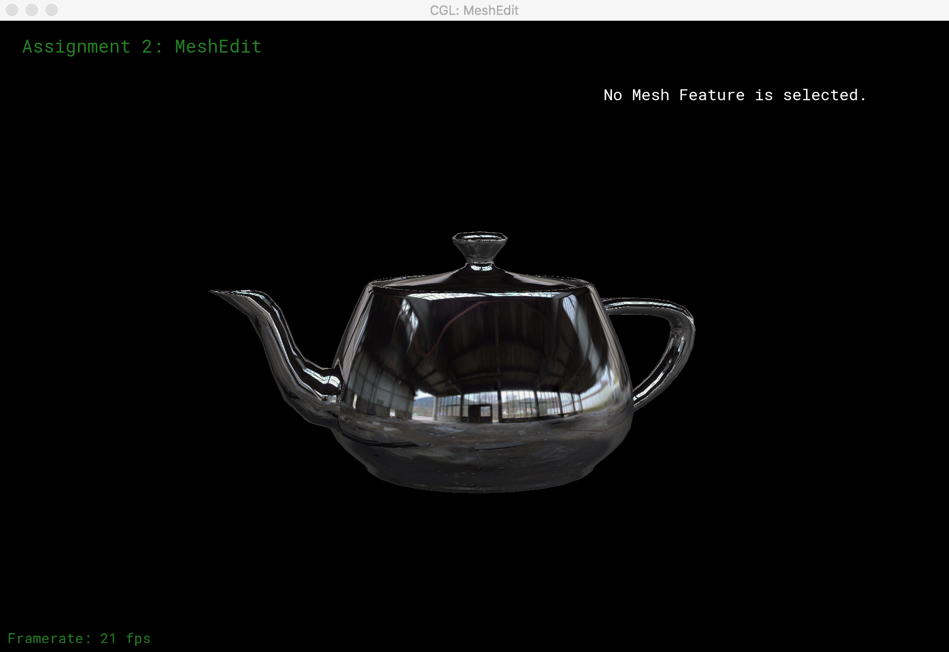
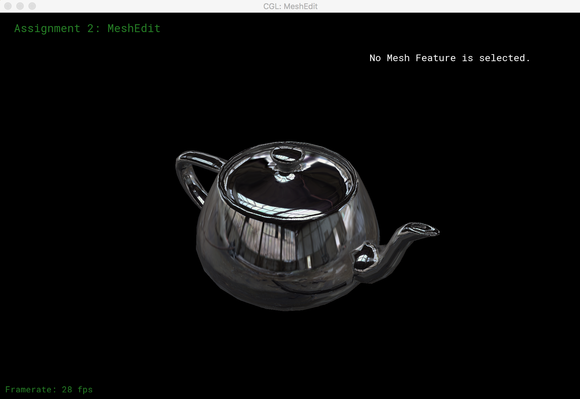
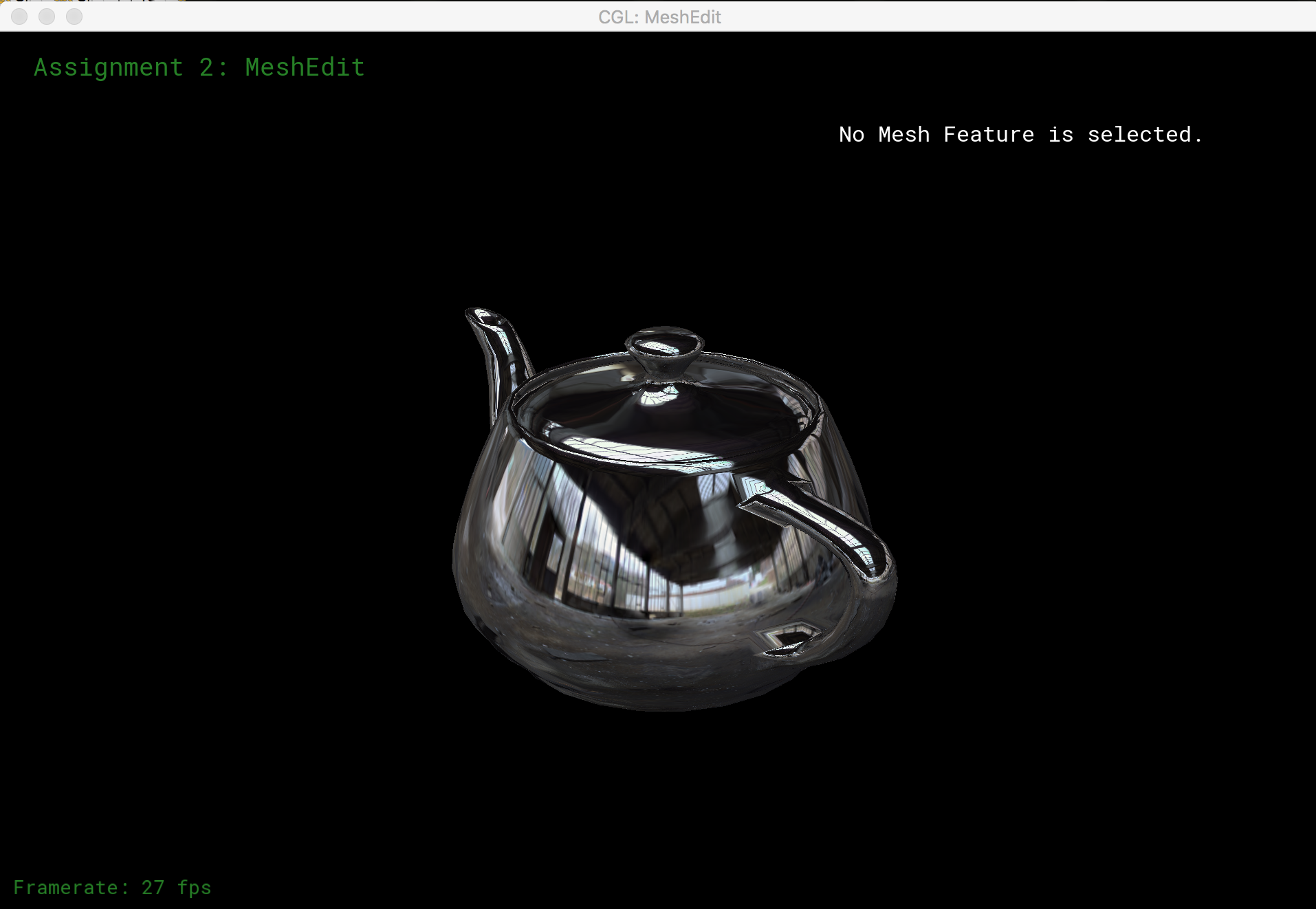
For environment mapping, the we compute the reflection direction from the surface normal vector and the vector towards eye position. The angles θ (angle between the vector projection on the xy plane and the x-axis) and ρ (angle between the vector project on either the xz or yz plane and the z-axis) are computed from the reflection vector, and used as texture coordinates for our envionrment texture file. The results of reflective environmental mapping are shown below.
